What "parallel" means for a Pylontech bank
Pylontech's low-voltage modules — US2000, US3000, US5000 and the Force-L1 family — are designed to be stacked. Bolt two or more together, wire them correctly, and the inverter sees one larger battery instead of several small ones. That's the whole point of a "bank": more kWh and more amps from units that ship in a size one person can carry.
This only applies to the low-voltage US-series line. Pylontech's high-voltage towers (Force H2, H48050) use a different, rack-based topology and aren't covered here.
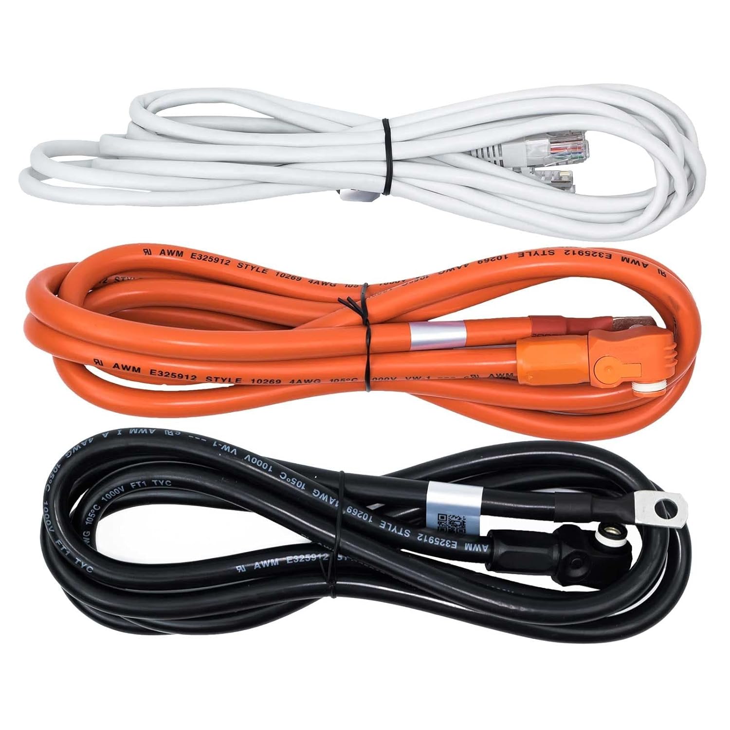
Two chains, two jobs: power and communication
Every battery added to a bank needs two connections, and it's easy to wire one correctly and forget the other matters just as much:
- Power. Positive and negative cables in parallel, battery to battery, carrying the actual charge/discharge current. Undersized or damaged power cabling is a fire and performance risk before it's a monitoring problem.
- Communication. A Console/Link daisy chain (RJ45) that lets the batteries agree on who's the master, share their internal state, and present themselves to the inverter as one coherent unit. This is the chain that fails quietly — no smoke, no smell, just an inverter that stops seeing part of the stack.
The master battery — the one connected to the inverter — is the only one whose Console port ever leaves the stack. Every other module talks only to its neighbours.
Addressing: how each battery knows which one it is
Batteries in the same bank need a unique address so the master can tell them apart when it reports per-module data upstream. On most US-series models this is a physical dip switch or rotary selector on the case; a handful of newer models auto-address over the Link chain. Either way, two things reliably cause problems: two modules left on the same address, and an address changed after the bank was already commissioned.
The cable that quietly breaks a bank
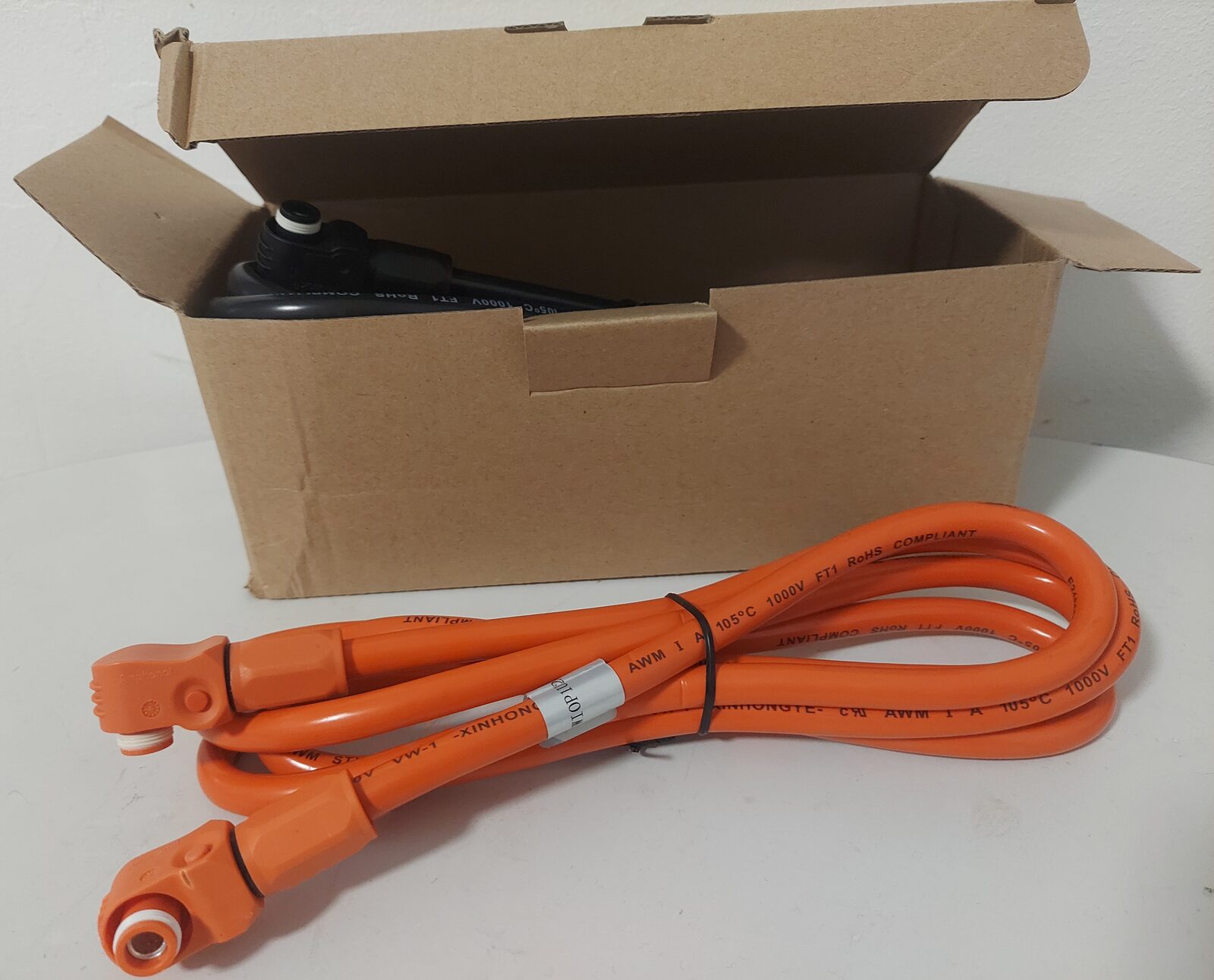
The RJ45 and power cables Pylontech ships in the box are sized for one specific layout: batteries stacked directly on top of each other. Real installs are rarely that tidy — a rack against a different wall than planned, a battery added later in a spot the original cable doesn't reach, an outdoor enclosure where the stock indoor-rated cable has no business being. The fix people reach for is a generic RJ45 patch lead or a random pair of power cables from a drawer, and that's exactly where a bank starts throwing intermittent communication faults or, worse, runs power cabling undersized for the current it now has to carry.
Pylon-Monitor doesn't sell cabling, but our sister companies do exactly this: ParallelCables.com and Cables-Solaires.com make correctly-rated Pylontech parallel cable sets — Amphenol connectors, proper gauge for the current, in 48cm, 70cm, 1m and 2m long-reach pairs — specifically for banks that don't fit the box-standard layout.
Common wiring mistakes as a bank grows
| Mistake | What it actually causes |
|---|---|
| Address collision | Two modules report as the same unit; per-module readings become unreliable or one module disappears from the stack. |
| Mixed models/capacities | Works, but the bank ages unevenly — the smaller or older module cycles harder and drifts from its siblings faster. |
| Undersized or over-length power cable | Voltage drop under load, heat at the connectors, and in the worst case a safety issue — this is not the place to improvise. |
| Comms cable under physical strain | Works on the bench, fails intermittently once the rack is closed up and the cable is pinched or stretched. |
| Wrong Link port used for the inverter connection | The stack won't present correctly to the CAN/RS485 side at all — covered in detail in the inverter guide. |
What monitoring a bank actually shows you
This is where the two chains matter again. Your inverter reads the CAN/RS485 link, and to it, a bank of one battery and a bank of sixteen look the same: one voltage, one current, one SOC. Anything happening to a single module inside the stack is invisible from there — a protocol limit, not a software one.
The Console chain is the only place per-module detail exists at all. Pylon-Monitor reads it from the master unit's Console port and reports up to 16 batteries individually — SOC, SOH, voltage, current, state and temperature per module, with a per-battery selector on the dashboard. (Per-cell voltage detail, a secondary reading, is capped at 64 values total — roughly the first four batteries; every other reading covers all 16.) In a bank, that per-module view is the difference between "the bank is fine" and "module 7 is quietly ageing faster than the rest."
Before you power on a new or expanded bank
- Every module has a unique address — verified, not assumed, especially after adding or moving one.
- Power cabling is rated for the bank's actual current, not just "the same as before."
- Comms cables reach without tension, coiling or being pinched when the enclosure closes.
- Only the master battery's Console port is connected onward — to the inverter or to a monitor, never both fighting over the same port.
- All modules are the same firmware version where the manufacturer requires it for mixed-capacity stacks.
Once it's running, the same eight-point check applies per module, not just to the bank as a whole — that's the whole argument for reading a stack per-battery instead of as one number.
Frequently asked questions
- Can Pylontech batteries be connected in parallel?
- Yes — that's how a Pylontech bank works. Low-voltage US-series modules (US2000, US3000, US5000, Force-L1) are designed to be wired in parallel, with a shared power connection and a Console/Link communication chain so the inverter sees one combined battery instead of several separate ones.
- How many Pylontech batteries can be chained together?
- It depends on the model and the inverter's own limit, but stacks of well over a dozen low-voltage modules are common. Pylon-Monitor, for instance, reads and reports up to 16 batteries individually from the master unit's Console port.
- Do all the batteries in a parallel bank need to be identical?
- Not strictly, but same-model, same-age batteries age far more evenly. Mixing capacities or generations works in most cases but the smaller or older unit tends to cycle harder and drift from the rest of the stack faster — worth watching per-module rather than assuming.
- Why does my inverter only show one battery when I have several wired together?
- Because the inverter reads the CAN/RS485 link, which deliberately presents the whole stack as a single virtual battery — one voltage, one current, one SOC. Per-module detail only exists on the Console chain, which the inverter doesn't use.
- What usually causes a communication fault in a Pylontech multi-battery setup?
- Far more often a cabling issue than a failed battery — an RJ45 run that's too long, stressed, or of the wrong spec for the layout, or an address collision after a module was added or moved. Checking the physical cable run is the first step before suspecting a module itself.
Pylon-Monitor reads every battery in your bank individually — SOC, SOH, voltage, current and temperature per module, up to 16 batteries chained from the master unit's Console port alone.
Order now — €59 One-time purchase, €59 total — no VAT, no subscription.