Short answer: a Pylontech module has four RJ45 sockets that do four different jobs. Your inverter uses CAN (sometimes RS485) to control charging, and that link sees the whole stack as one battery: no cell voltages, no health per module. The Console port is a separate RS-232 line where the BMS answers with full detail, and almost no installation uses it after commissioning day. Reading it does not disturb the inverter, whatever the brand.
Your inverter already talks to the battery. So why can't you see anything?
Every hybrid inverter running a Pylontech stack is in constant contact with the BMS. It knows the pack voltage, the current, and when to stop charging. Yet as soon as you want one cell's voltage, the health of module 3, or why one unit runs two degrees warmer than the others, there is nothing. Not on the inverter's screen, not in the installer's app, even though the battery is right in front of you.
Your hardware is not the problem. There are two separate conversations on two separate ports, and this guide is about telling them apart.
Four RJ45 sockets, four different jobs
The front of a low-voltage Pylontech module is full of what look like network sockets. None of them is Ethernet. They carry four unrelated protocols, and plugging the wrong cable into the wrong socket is the most common installation mistake we come across.
| Port | What it carries | Who normally uses it |
|---|---|---|
| CAN | CAN bus: the standard control link between battery and inverter | Your inverter |
| RS485 A / B | RS485 serial: the alternative inverter link, also used by some vendor tools | Your inverter, or nothing |
| CONSOLE | RS-232 text console at 115200 baud: the BMS's own diagnostic shell | Almost always nobody |
| LINK PORT 0 / 1 | The internal link between modules in a stack | The batteries themselves |
What the inverter link carries, and what it leaves out
The CAN or RS485 link between battery and inverter exists for one reason: to let the inverter charge and discharge the pack safely. It is a control conversation and it is deliberately narrow. It usually carries the overall state of charge, the pack voltage, the total current, the charge and discharge limits the BMS currently allows, and a few alarm and protection flags.
All of these describe the whole stack as one virtual battery. That is exactly what the inverter needs, and it is why the following never shows up on your inverter, however good its display:
- State of health per module: one ageing unit in a stack of six disappears in the average.
- Individual cell voltages: the earliest warning there is, and the inverter never receives it.
- Temperature per module, including the differences between modules, which often say more than any absolute figure.
- Cycle count per module: handy in a warranty discussion, absent from the control link.
- Which module triggered a protection.
Pylontech is not hiding anything. The BMS knows all of it. The inverter protocol was simply not designed to carry it.
The Console port: the one nobody uses
The Console port is a plain RS-232 serial line at 115200 baud, with a small text shell built into the BMS firmware behind it. You send a short command and it answers with a table. pwr returns one line per battery in the stack. bat 1 returns the cell voltages of unit 1. soh 2, info 3, stat work the same way, module by module.
It is the port Pylontech's own console software connects to, which is why it exists. Since most installations use that software exactly once, on commissioning day, from a laptop, the Console port then spends the rest of the battery's life doing nothing.
Above all, it is a separate physical interface from CAN and RS485. Using it takes nothing away from the inverter.
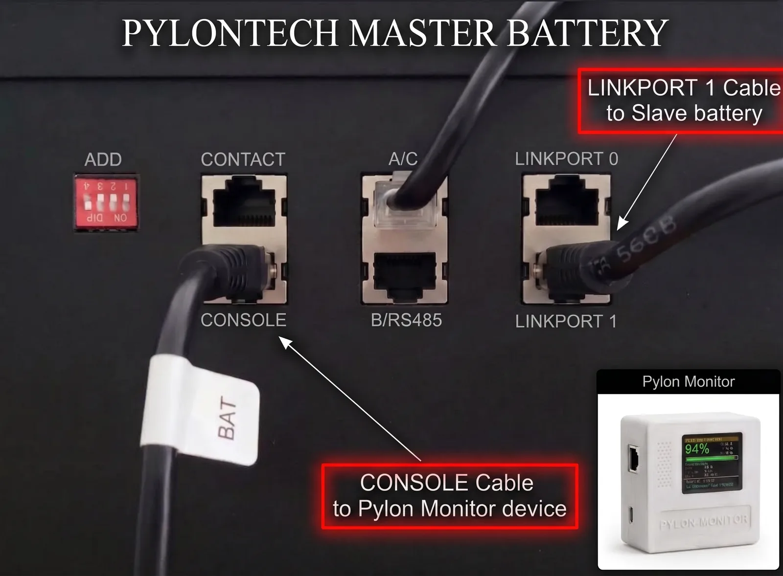
The cable that chains your master battery to the first slave must leave LINK PORT 1 on the master — never LINK PORT 0. It plugs into LINK PORT 0 on the slave, and every further battery repeats the same 1 → 0 pattern. Wired the other way round the master never sees the rest of the stack, so Pylon-Monitor reports a single battery no matter how many you own.
Which link does my inverter use?
Almost every hybrid inverter that supports Pylontech uses the CAN port. A few use RS485 and some can be set either way. For this guide, the column that matters is the last one, and it is the same on every row.
| Inverter | Battery link normally used | Console port still free? |
|---|---|---|
| Victron (Cerbo GX / Venus GX) | CAN, via BMS-Can / VE.Can | Yes |
| Deye / Sunsynk | CAN | Yes |
| Growatt SPF / SPH | CAN or RS485 | Yes |
| Sofar | CAN | Yes |
| Solis | CAN | Yes |
| SMA Sunny Island | CAN | Yes |
| Voltronic / Axpert / MPP Solar | RS485 or CAN | Yes |
| Studer (Xcom-CAN) | CAN | Yes |
Take the middle column as a guide, not a wiring diagram: the exact port, cable pinout and protocol setting depend on the model and firmware version, and your inverter's manual is the reference. The right-hand column never changes. Whatever bus your inverter took, it did not take the Console port.
No, it will not fight with your inverter
This is the question we get asked most, so here is the direct answer. Reading the Console port does not interfere with the inverter link, because:
- They are different ports. Not a shared bus, not a splitter, not a Y cable: a separate socket with its own interface on the BMS.
- Monitoring only asks questions. It sends
pwr,batandsohand reads the answers. It does not send charge settings or control frames to the inverter link. - The inverter never sees it. Its CAN or RS485 conversation continues exactly as before, with the same timing and the same data.
The same reasoning answers the warranty question: the Console port is a documented diagnostic interface, and reading from it is what it is there for. Nothing is modified, flashed or overridden. If your installer looks after the system under a service contract, it costs nothing to let them know.
When the two disagree, and why that is usually normal
Sooner or later you will see the inverter showing 62% while the battery's console says 64%. It is almost never a fault. The inverter's figure is its own working number: many inverters apply their own coulomb counting, smoothing or correction on top of what the BMS reports, and some keep a margin at each end of the range on purpose.
The console figure is the BMS's own, unfiltered. When you are diagnosing the battery, that is the one you want. When you are wondering why the inverter stopped charging at 97%, the inverter's figure is the relevant one. Both are right; they answer different questions.
Stacked batteries: the mistake almost everyone makes
One point catches out a large share of multi-battery installs, and it belongs here because it looks like a monitoring fault when it is really a wiring one. Whether you read the stack from the inverter or from the Console port, everything comes to you through the master module. If the stack itself is chained wrong, only the master exists for any tool.
The chain cable must leave LINK PORT 1 on the master and go into LINK PORT 0 on the first slave, then repeat that 1 → 0 pattern down the stack. Wired the other way round, the master never sees the rest of the stack, and every tool you connect, the inverter included, reports one battery however many you have. The full sequence is in our installation guide.
Reading the Console port without taping a laptop to the wall
Knowing the port is free is one thing; using it all the time is another. A serial console is a manual tool. It answers when asked, from a machine cabled to the battery, and it does not remember yesterday. Fine for commissioning, useless for noticing that the cell spread has been rising for three weeks.
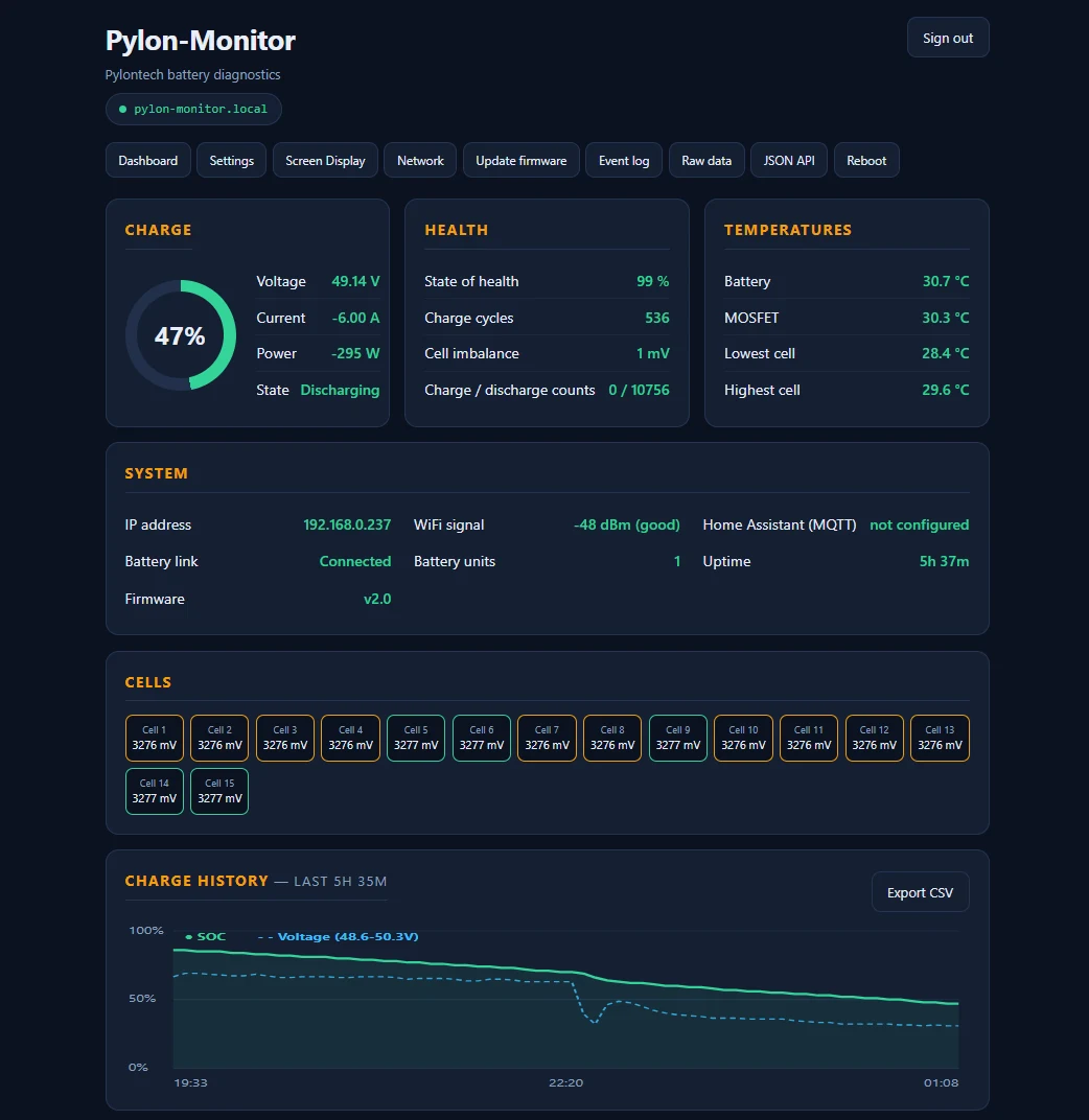
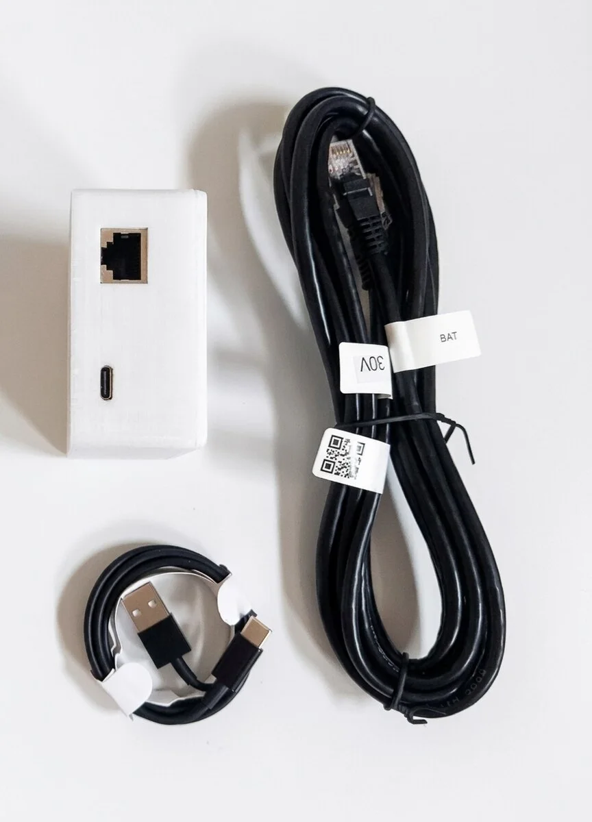
Making that port permanent takes a small device that stays plugged into CONSOLE, queries the shell on a schedule and republishes the result where you actually look: a local dashboard, a Home Assistant entity, a Node-RED or Jeedom flow, or a plain JSON endpoint your own script can read. That is what Pylon-Monitor does. Once the data flows, knowing which numbers deserve an alarm becomes the interesting part. If you are still weighing up the whole idea, start with our monitoring guide.
Frequently asked questions
Can I use the Pylontech Console port while my inverter is connected over CAN or RS485?
Yes. The Console port is a physically separate RS-232 interface on the BMS, not a branch of the CAN or RS485 bus. Reading it changes nothing about the inverter link: the inverter keeps the same conversation, the same timing and the same data it had before.
What is the difference between the Pylontech CAN port and the Console port?
The CAN port carries a narrow control conversation for the inverter: overall pack state of charge, pack voltage, total current, the charge and discharge limits the BMS allows, and alarm flags — the whole stack described as one virtual battery. The Console port is an RS-232 diagnostic shell at 115200 baud that answers per-module queries, including individual cell voltages, per-module state of health, temperatures and cycle counts.
Does connecting to the Pylontech Console port void the warranty?
The Console port is a documented diagnostic interface, and reading from it is exactly what it is designed for. Nothing is modified, flashed or overridden — monitoring sends queries and reads the answers. If your installer maintains the system under a service contract, it is still worth mentioning it to them.
Why does my inverter show a different state of charge than the battery?
Because the two numbers are produced differently. Many inverters apply their own coulomb counting, smoothing or a manufacturer-specific correction on top of what the BMS reports, and some deliberately reserve a margin at each end of the range. The Console figure is the BMS's own, unfiltered. A gap of a few percent is normal, not a fault.
Which Pylontech batteries have a Console port?
The low-voltage US series and its relatives — US2000, US2000B+, US2000C, US3000, US3000C, US5000, UP2500 and the Force-L1 family. High-voltage models such as the Force-H range use a different architecture and are not covered here.
Can I plug a Pylontech RJ45 port into a network switch or router?
No. Every RJ45 socket on a Pylontech module carries CAN, RS485 or RS-232 — never Ethernet. The connector fits a router port perfectly, which is exactly why the mistake is common; nothing good comes of it. Match each cable to the labelled port instead.
Frequently asked questions
- Can I use the Pylontech Console port while my inverter is connected over CAN or RS485?
- Yes. The Console port is a physically separate RS-232 interface on the BMS, not a branch of the CAN or RS485 bus. Reading it changes nothing about the inverter link: the inverter keeps the same conversation, the same timing and the same data it had before.
- What is the difference between the Pylontech CAN port and the Console port?
- The CAN port carries a narrow control conversation for the inverter: overall pack state of charge, pack voltage, total current, the charge and discharge limits the BMS allows, and alarm flags — the whole stack described as one virtual battery. The Console port is an RS-232 diagnostic shell at 115200 baud that answers per-module queries, including individual cell voltages, per-module state of health, temperatures and cycle counts.
- Does connecting to the Pylontech Console port void the warranty?
- The Console port is a documented diagnostic interface, and reading from it is exactly what it is designed for. Nothing is modified, flashed or overridden — monitoring sends queries and reads the answers. If your installer maintains the system under a service contract, it is still worth mentioning it to them.
- Why does my inverter show a different state of charge than the battery?
- Because the two numbers are produced differently. Many inverters apply their own coulomb counting, smoothing or a manufacturer-specific correction on top of what the BMS reports, and some deliberately reserve a margin at each end of the range. The Console figure is the BMS's own, unfiltered. A gap of a few percent is normal, not a fault.
- Which Pylontech batteries have a Console port?
- The low-voltage US series and its relatives — US2000, US2000B+, US2000C, US3000, US3000C, US5000, UP2500 and the Force-L1 family. High-voltage models such as the Force-H range use a different architecture and are not covered here.
- Can I plug a Pylontech RJ45 port into a network switch or router?
- No. Every RJ45 socket on a Pylontech module carries CAN, RS485 or RS-232 — never Ethernet. The connector fits a router port perfectly, which is exactly why the mistake is common; nothing good comes of it. Match each cable to the labelled port instead.
Pylon-Monitor plugs into the Console port your inverter never uses: SOC, SOH, cell voltages and temperatures per module on a live dashboard, without changing anything on your CAN or RS485 link.
Order now — €59 One-time purchase, €59 total — no VAT, no subscription.